English
 Charge
Prepared steel, iron or alloy charge is loaded into a correctly lined furnace crucible.

Dinghong manufactures heavy-duty steel shell induction furnaces with rigid welded structures, magnetic yokes and model-specific tilting systems. Configure the furnace body, power supply, cooling and auxiliary equipment around your metal, batch capacity, target output and local electrical conditions.
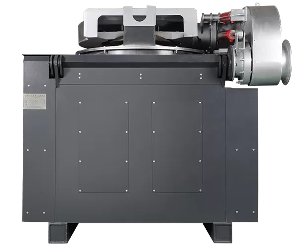
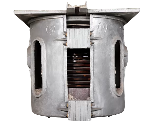
The DHG steel shell furnace is an intermediate-frequency induction melting furnace designed for repeated foundry production. Its welded steel structure supports the induction coil and magnetic yokes, while the tilting system is selected according to furnace capacity and operating requirements.
As an induction metal melting furnace, the system converts electrical energy into heat inside the metal charge without direct fuel combustion. It is suitable for projects that require controlled batch melting, flexible start and stop, and integration with a matched power supply, cooling circuit, hydraulic equipment and dust extraction system.
A welded steel frame provides mechanical support for demanding operating cycles and large-capacity furnace bodies.
Capacity, power, frequency, cooling and tilting are matched to the metal and production target.
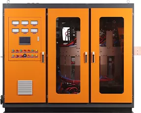
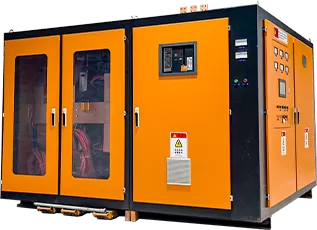
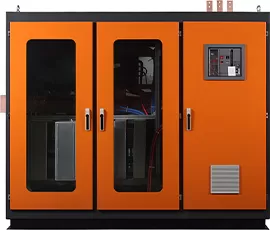
Dinghong can combine the furnace body with power, control, cooling and auxiliary equipment.
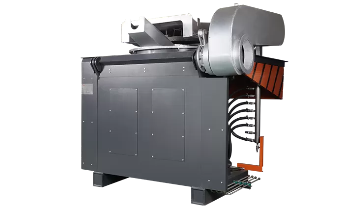
A medium-frequency induction melting system transfers energy through the coil and creates induced currents inside the charge, producing rapid internal heating and natural electromagnetic stirring.
Prepared steel, iron or alloy charge is loaded into a correctly lined furnace crucible.
The matched power supply energizes the water-cooled coil and creates an alternating magnetic field.
Induced currents heat the metal while the operator controls power, temperature and production timing.
The configured tilting mechanism transfers molten metal to the ladle or casting process.
Select the nominal furnace capacity together with the required production rate, metal type and matched power supply. A larger crucible alone does not determine tons per hour; melting output also depends on power, charge condition, tapping temperature and operating schedule.
| Model | Shell Plate mm | Copper Tube mm | Coil Inner Dia. mm | Loading Height mm | Coil Weight kg | Yokes pcs | Yoke Weight kg/pc |
|---|---|---|---|---|---|---|---|
| 0.5T | 12 | 5–6 | 550 | 1000 | 165 | 6 | 105 |
| 0.75T | 12 | 5–6 | 630 | 1000 | 185 | 6 | 145 |
| 1T | 12 | 5–6 | 700 | 1100 | 250 / 260 | 6 / 8 | 150 × 6 pcs / 125 × 8 pcs |
| 1.5T | 12 | 5–8 | 760 | 1200 | 318 | 8 | 165 |
| 2T | 12 | 5–8 | 820 | 1280 | 358 | 8 | 188 |
| 2.5T | 12 | 5–8 | 900 | 1280 | 395 | 8 | 245 |
| 3T | 16 | 5–8 | 920–950 | 1500 | 460 | 10 | 240 |
| 5T | 16 | 5–8 | 1150–1200 | 1650 | 620 | 10 | 410 |
| 8T | 20 | 8 | 1350 | 2000 | 985 | 12 | 520 |
| 10T | 25 | 8 | 1420 | 2200 | 1500 | 12 | 585 |
| 20T | 30 | 8 | 1760 | 2650 | 3500 | 14 | 680 |
| Model | Yoke Size mm | Furnace with Reducer m | Furnace with Hydraulic Unit m | Furnace Weight t | Hydraulic Unit Size mm | Hydraulic Unit Weight t |
|---|---|---|---|---|---|---|
| 0.5T | 1000 × 220 | 1.8 × 1.5 × 1.35 | — | 2.8 | — | — |
| 0.75T | 1000 × 280 | 1.8 × 1.5 × 1.45 | — | 3 | — | — |
| 1T | 1100 × 300 (6 pcs) 1100 × 220 (8 pcs) | 2 × 1.5 × 1.55 | 2.5 × 2.3 × 1.83 | 4.7 | 1000 × 800 × 1300 | 0.6 |
| 1.5T | 1200 × 240 | 2 × 1.5 × 1.6 | By configuration | 5.7 | 1000 × 800 × 1300 | 0.6 |
| 2T | 1280 × 270 | — | 2.7 × 2.7 × 2.1 | 6.7 | 1000 × 900 × 1300 | 0.8 |
| 2.5T | 1280 × 310 | — | 2.7 × 2.7 × 2.1 | 7.2 | 1000 × 900 × 1300 | 0.8 |
| 3T | 1500 × 270 | — | 2.8 × 3.1 × 2.3 | 9.5 | 1000 × 900 × 1400 | 0.8 |
| 5T | 1700 × 310 | — | 3.1 × 3.3 × 2.65 | 13 | 1200 × 1000 × 1400 | 0.9 |
| 8T | 2000 × 320 | — | 3.5 × 3.8 × 3 | 18 | 1200 × 1000 × 1400 | 0.9 |
| 10T | 2200 × 360 | — | 3.6 × 4 × 3.3 | 20 | 1800 × 1200 × 1400 | 1.5 |
| 20T | 2600 × 370 | — | 4.3 × 4.65 × 3.9 | 43 | 2000 × 1500 × 1400 | 2.2 |
Dimensions are shown as length × width × height. Specifications may be adjusted to suit the final power, lining, metal and installation conditions.
Send the metal, batch size, required tons per hour and local voltage for a model and power recommendation.
A 1 ton, 2 ton, 5 ton or 10 ton induction furnace describes nominal batch capacity—not guaranteed hourly production. The right system begins with the production requirement and then matches furnace capacity, electrical power, cooling and operating arrangement.
A complete induction melting furnace system can be configured with the furnace, matched power supply, transformer, cooling, tilting, control and environmental equipment required for the project. The exact scope is clearly defined in the technical quotation.
Rigid welded shell, induction coil, magnetic yokes, lining area and tilting structure selected for the furnace capacity.
View furnace models →Series or parallel power configuration matched to the metal, furnace capacity and production target.
Explore power supplies → ElectricalVoltage conversion, isolation, capacitors, reactor and busbar arrangement based on the local grid and system design.
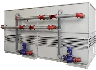
View transformer functions → CoolingCooling capacity and water conditions are matched to the power supply, coil and site environment.
View cooling solutions → PouringHydraulic control supports stable furnace tilting for appropriate capacities; smaller models may use a reducer configuration.
View hydraulic equipment → EnvironmentFurnace cover, dust hood and front control table can be integrated around pouring access and plant extraction requirements.
View dust extraction hood →Define the equipment scope before comparing quotations from different suppliers.
The rigid steel shell, long-arc magnetic yokes, model-specific tilting system and cyclonic dust hood are designed to improve furnace durability, energy utilization, operator protection and environmental control in demanding foundry production.
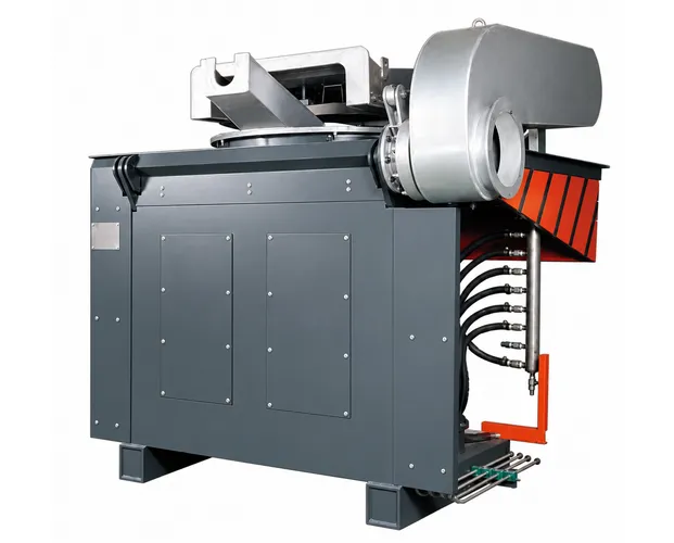
The sturdy welded steel frame supports the coil assembly and resists the thermal and mechanical loads of repeated melting cycles, making it especially suitable for large-capacity furnaces where rigidity and operating safety are priorities. Aluminum shells can experience metal-toughness fatigue and progressive deformation under sustained heat, heavy loads and strong magnetic fields; in intensive foundry conditions, serious wear may appear after about one year. The rigid structure and lower magnetic leakage help the steel shell furnace achieve a substantially longer working life.
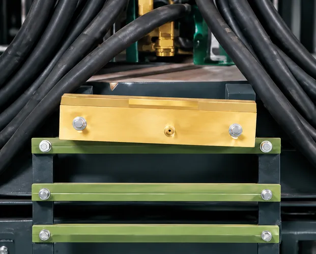
Silicon-steel yokes shield the coil-generated magnetic field, reduce external magnetic resistance and limit leakage flux at the coil ends. Their arc-shaped inner faces fit closely against the coil wall, increasing the effective magnetic-conduction area and supporting the coil. Together with the forward-and-reverse winding coil design, this arrangement improves system efficiency and can save approximately 5%–8% energy under matched operating conditions.
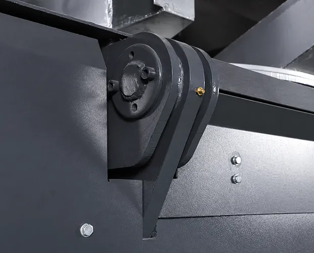
The steel shell better resists deformation under high temperature and heavy molten-metal loads. Applicable models use a controlled hydraulic tilting system for safe, reliable pouring. During furnace tipping, the anti-fall protection cover rises automatically to form a protective guard and reduce the risk of personnel falling into the operating area.
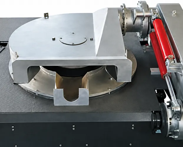
The compact cyclonic dust-removal furnace cover collects fumes close to the source while retaining heat, reducing heat loss and improving equipment safety. It occupies less workshop space, tilts forward and backward, and can be held at any required position for charging, treatment and maintenance. For ductile-iron production, it can also capture dust generated during in-furnace spheroidization—an emission point that conventional fixed dust hoods typically cannot cover effectively.
Review the furnace structure, tilting method, extraction and workshop conditions with our project team.
Furnace power, lining, coil design and process settings must be confirmed for the intended metal. Share the metal grade and production target before selecting the final configuration.
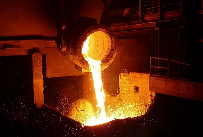
Controlled batch melting for steel casting and foundry production.
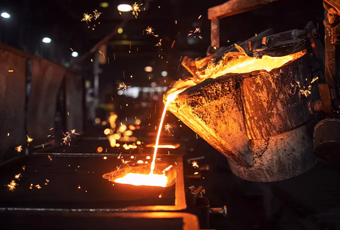
Configuration according to alloy grade, temperature and lining practice.
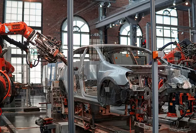
Melting solutions for grey iron, ductile iron and component foundries.
Project review for composition, charge, temperature and casting route.
Melting systems for steel, iron and alloy casting operations.
View Application →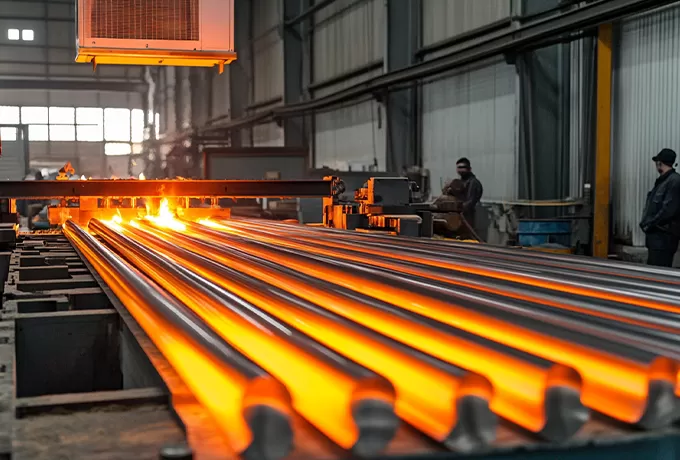
Related billet and bar heating systems for forging lines.
View Application →
Melting, alloying and heating solutions for metal processing.
View Application →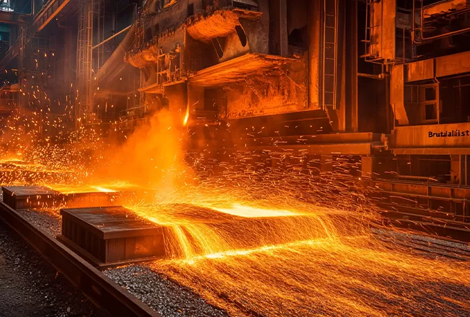
Related induction hardening, heating and thermal-processing solutions.
View Application →
Systems supporting automotive casting, forging and component production.
View Application →
Heating and melting systems for metal products used in construction.
View Application →Provide the metal grade, tapping temperature and charge material so the power and lining requirements can be reviewed.
Both furnace types use electromagnetic induction. When comparing the heavy-duty steel structure with an Aluminum Shell Furnace, the appropriate choice depends on capacity, production intensity, tilting requirements, workshop conditions and investment priorities.
| Selection Factor | Steel Shell Furnace | Aluminum Shell Furnace |
|---|---|---|
| Typical priority | Structural rigidity and heavy-duty production | Compact structure and installation flexibility |
| Capacity range | Often selected for medium and large capacities | Often selected for smaller and moderate capacities |
| Tilting arrangement | Hydraulic configurations commonly available | Reducer configurations commonly used |
| Metal and process | Frequently selected for steel and iron foundries | Common in smaller foundries and non-ferrous projects |
| Final decision | Confirm against metal, output, furnace capacity, duty cycle, safety plan and total system cost. | |
There is no single price for every steel shell induction furnace. A reliable quotation defines the furnace, electrical system, cooling, auxiliary equipment and service scope required by the production project.
Send your production requirements to receive a defined configuration and quotation.
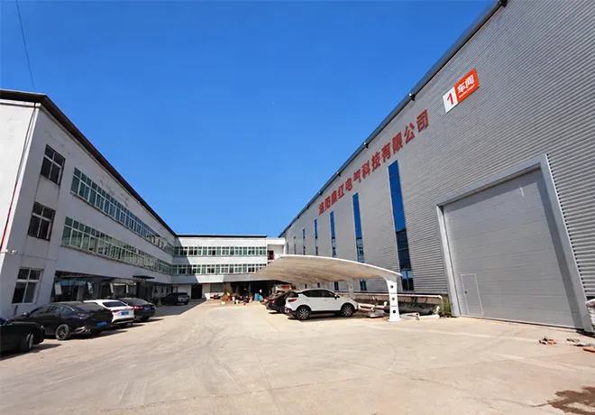
Luoyang Dinghong Electric Technology Co., Ltd. designs and manufactures medium-frequency induction furnaces, power supplies and complete industrial heating systems for foundry, metallurgy, machinery and metal-processing projects.
The project team can review the production requirement, configure the furnace and supporting system, prepare technical documentation, and provide manufacturing and after-sales support.
View the company brochure for an introduction to Dinghong, its induction furnace portfolio, supporting equipment and industrial solutions.
Metal, output, voltage and plant conditions are confirmed before selection.
Furnace, power, cooling, tilting and auxiliary equipment are matched.
Key furnace and electrical assemblies are produced to the approved design.
Mechanical, cooling, electrical and operating checks are completed before delivery.
Drawings, manuals, packing, installation guidance and spare-parts support are prepared.
It is a coreless electric induction furnace with a rigid welded steel outer structure. A medium-frequency power supply energizes the induction coil, generating induced currents that heat and melt the metal charge inside the lined crucible.
The furnace can be configured for carbon steel, stainless steel, cast iron and selected alloys. The power rating, operating frequency, refractory lining and process parameters must be confirmed for the specific metal and grade.
Start with the required molten metal per batch and the total tons needed per hour or per day. The final choice also depends on melting time, working hours, charge condition, furnace arrangement and available electrical capacity.
The furnace can be supplied with a matched medium-frequency power supply. The quotation should clearly identify the furnace body, power cabinet, transformer, capacitors, reactor, cooling and all auxiliary equipment included in the project scope.
A project may include the steel shell furnace, power supply, transformer, compensation components, cooling system, tilting equipment, control table, furnace cover, dust extraction hood, cables, water connections, spare parts and technical documentation. The final scope is project-specific.
Price depends on metal, capacity, required output, power rating, electrical topology, furnace quantity, tilting method, cooling, control, environmental equipment, delivery destination and service scope. Send these details for a comparable technical quotation.
Hydraulic tilting is available for appropriate furnace capacities and production requirements. Some smaller models may use a reducer. Dinghong confirms the tilting configuration together with the furnace model and pouring process.
Please provide the metal and grade, capacity per batch, hourly or daily production target, working hours, charge material, tapping temperature, local voltage and frequency, installation country and required supply scope.
Dinghong provides project support from design and manufacturing through technical documentation and after-sales assistance. Confirm the required installation, commissioning and training scope when requesting the quotation.
Compare matched power supplies, an alternative furnace-body structure and supporting heating or cooling equipment when defining the complete project scope.
Send the metal, furnace capacity, production target and local voltage for a complete system recommendation.
Explore practical guidance for operating induction furnaces, reviewing manufacturers and evaluating complete melting-system suppliers.
 September 02, 2026
Review preparation, charging, temperature control, pouring and routine practices for a safer and more consistent melting process.
Read Article → August 30, 2026
Learn which engineering, manufacturing, documentation and service capabilities matter when evaluating an induction-equipment partner.
Read Article →
August 28, 2026Compare supplier capability by system matching, technical documentation, quality control, commissioning support and project experience.
Read Article →Tell us what you melt, how much you need per batch and your production target. Our team will review the furnace capacity, power supply and complete system scope required for your project.